Knowledge

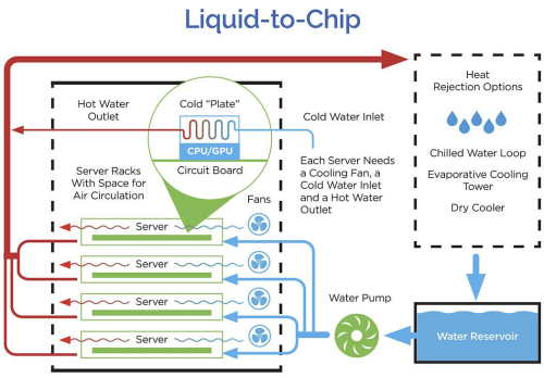
Cold plates circulate coolant through narrow internal channels to remove heat from high-power processors.This compact design supports efficient heat transfer, but it also makes the cooling path more sensitive to particles and deposits in the coolant.

When particulate contamination builds up inside these passages, it can cause cold plate fouling, reduce the available flow area, and increase resistance to coolant flow. The effect may develop gradually, so a cooling loop can continue operating even as individual flow paths become less effective.

For data center liquid cooling systems, controlling particles is therefore not only a coolant cleanliness issue. It is also part of maintaining consistent flow and thermal performance.

Why Cold Plates Are Sensitive to Particle Contamination

Cold plates use relatively small internal channels to bring coolant close to the heat-generating surfaces. The smaller the flow path, the less space there is for particles to pass through without affecting the channel.

A particle that moves easily through a larger section of TCS piping may become trapped when it reaches a narrower passage. Particles can also collect around changes in geometry, channel entrances, bends, or other areas where local flow conditions allow material to settle.

This is why contamination can become more significant inside a cold plate than it appears in the main cooling loop. Several factors affect the level of risk, including particle size and concentration, cold plate geometry, coolant velocity, and the overall condition of the TCS.

Why Cold Plates Are Sensitive to Particle Contamination

How Particle Buildup Restricts Cold Plate Flow

Particles can collect in the narrow flow passages of a cold plate, reducing the space available for coolant flow. Early buildup may have little noticeable effect during normal operation. As more particles collect, flow resistance increases and the affected passage may no longer deliver the required coolant flow. The effect can vary across systems with multiple parallel cooling paths.

One cold plate or branch may see more restriction than another, even when they are connected to the same TCS. Uneven restriction can result in an imbalance in coolant flow across the system.A complete blockage is not required to affect performance. Partial restriction can be enough to reduce flow through a cold plate when the system requires a defined flow rate to maintain the intended thermal performance.

How Particle Buildup Restricts Cold Plate Flow

Cold Plate Fouling and Cooling Performance

Cold plate fouling can affect cooling performance in more than one way.

When a flow passage becomes restricted, the amount of coolant reaching part of the cold plate may decrease. If deposits also build up on heat-transfer surfaces, they can add resistance between the heat source and the coolant.

The result can be a gradual change in the thermal behavior of the system. Depending on the system design, engineers may see:

  • Reduced flow through an individual cooling path
  • Increasing pressure drop
  • Uneven flow between parallel branches
  • Higher coolant or component temperatures
  • Changes in cold plate thermal performance
  • More frequent filter maintenance

These symptoms are not specific to particle contamination. Pump conditions, valves, air, coolant properties, and other system variables can also influence flow and temperature.

For this reason, changes in pressure, flow, and temperature should be considered together when investigating a liquid cooling system.

Where Contamination Can Affect the Cooling Loop

Cold plates are not the only components that can be affected by particles.

Smaller flow openings throughout the TCS can also collect or retain contamination. Particles can be found in:

  • Cold plate channels
  • Quick-disconnects
  • Valves
  • Fittings
  • Screens and strainers
  • Heat exchanger passages
  • Other small flow paths

The location of particle buildup depends on the system design and the characteristics of the contamination.

Monitoring Flow and Pressure Changes

Changes in flow and pressure can provide useful indications of developing restrictions.

For example, a rising differential pressure across a filter can indicate that the filter is retaining more particulate material. Changes in flow or pressure across individual branches may also indicate that resistance is developing somewhere in the cooling path.

Monitoring should be based on the actual TCS design. Useful parameters may include:

  • Filter differential pressure
  • System pressure
  • Branch flow rate
  • Coolant temperature
  • Particle levels or coolant cleanliness indicators

These measurements can help distinguish a gradual contamination problem from other causes of changing cooling performance.

The objective is to identify changes early, before contamination develops into a more difficult maintenance or cooling issue.

How Filtration Helps Control Cold Plate Fouling

TCS filtration is one part of maintaining coolant quality and protecting sensitive components.

The filtration system needs to capture particles that could affect sensitive components while keeping pressure loss within an acceptable range. Selecting a filter only by micron rating is therefore not enough.

The system also needs to consider:

  • Required flow rate
  • Particle size and loading
  • Allowable pressure drop
  • Coolant chemistry
  • Material compatibility
  • Available installation space
  • Filter service requirements
  • Location within the cooling loop

The required filtration level should also be considered together with the cold plate design. As noted by the Open Compute Project, filter selection depends on system design, component geometry, and filter location. Excessive pressure drop across the filter can reduce the efficiency of the overall system.

For some applications, cartridge filtration or high-flow filtration may be appropriate. Bag filtration or self-cleaning filtration can also be considered where flow, contamination load, or maintenance requirements call for a different approach.


How Particle Contamination Restricts Cold Plate Flow

Choosing Filtration for a TCS

There is no single filtration configuration that applies to every liquid-cooled data center.

A suitable approach depends on the cooling architecture, cold plate requirements, coolant, flow conditions, contamination level, and available pressure-drop margin.

For OEMs and liquid cooling integrators, the filtration point should also be considered as part of the overall TCS design. Filtration should be located where it can control particles effectively and still allow easy access for monitoring and maintenance. This ensures the protection of downstream components while avoiding any additional flow resistance.

The goal is not to use the finest filter possible. The filter needs to remove the particles that matter without reducing the coolant flow needed by the system.

Maintaining the Designed Flow Path

Cold plates rely on coolant moving through small internal passages. Particle buildup in these passages can change the way coolant moves through the cold plate.

Particle control is therefore part of TCS design and operation.

When setting up filtration, engineers also need to account for particle levels, cold plate geometry, flow requirements, pressure drop, and maintenance. The filtration setup needs to work with the cooling system, not against it.

For data center liquid cooling systems that require a closer review of filtration requirements, contact BOLEFIL to evaluate TCS filtration based on flow conditions, particle control requirements, coolant compatibility, and available pressure-drop margin.

relevant products

Subscribe to our blog newsletter

Get the best, coolest and latest delivered to your inbox each week

[newsletter_form]

Have Questions?

error: Content is protected !!