
Knowledge

CDU filter pressure drop can change significantly as a filter moves from a clean condition to a loaded condition. That change can affect the hydraulic margin available to the rest of the liquid cooling system, particularly when the CDU is already operating close to its required flow and pressure conditions.

This is where CDU filter pressure drop needs to be considered beyond a single value on a datasheet. The pressure loss of a clean filter is only the starting condition. As the filter retains particulate, differential pressure changes, and the filtration assembly becomes a larger part of the hydraulic resistance in the TCS loop.

For CDU filter sizing, the difference between these operating conditions can affect how much pump head remains available for the rest of the cooling circuit.

Clean Pressure Drop in CDU Filter Sizing

A clean filter pressure drop describes the resistance of a new filter at a specified flow rate and test condition. It is normally one of the first values reviewed when a filter is considered for a liquid cooling application.

At this stage, the filter has not accumulated a significant amount of particulate, so the measured pressure loss primarily reflects the filter media and the flow path through the new assembly.

This value is useful when establishing the initial hydraulic condition of a CDU. The filter is installed in the same flow path as the other TCS components, so its pressure loss has to be considered alongside the resistance of piping, fittings, heat exchangers, manifolds, cold plates, valves, and other components.

The available pump head is not unlimited. If the CDU requires a defined flow rate through the TCS loop, the pressure consumed by filtration reduces the portion of the pump’s available head that can be used elsewhere in the circuit.

A low clean pressure drop can therefore provide useful hydraulic margin at the beginning of operation. It does not, however, indicate how that margin will change as the filter loads.

What Changes as a CDU Filter Loads

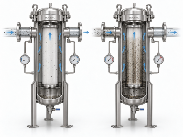
Once the cooling system is operating, the filter begins retaining suspended particulate. The retained material changes the flow resistance through the filter media, causing differential pressure to increase.

This is the loaded filter pressure drop.

The rate of increase is not necessarily constant throughout the filter’s service life. A filter may operate with relatively little change in ΔP during an initial period and then experience a faster increase as more particulate accumulates.

The contamination entering the system also affects the loading behavior. A CDU during initial commissioning may encounter installation debris, flushing residue, or other particulate that is not representative of the stabilized cooling loop. After commissioning, the particle load may be lower or have a different composition.

As a result, the same filter can experience different loading behavior in different applications even when its nominal filtration rating remains unchanged.
What Changes as a CDU Filter Loads

Comparing CDU Filter Pressure-Drop Data

Pressure-drop values from different filter suppliers are useful only when their test conditions and measurement basis can be compared.

Flow rate is an obvious variable. A pressure-drop value measured at one flow condition cannot simply be treated as a fixed value across the operating range.

The fluid used during testing also matters. Water and glycol-based coolants can produce different pressure-drop behavior because their physical properties are different. The pressure drop can also change with temperature because fluid viscosity varies.

The filter configuration needs to be considered as well. A pressure-drop curve generated for one filter size, element configuration, or flow path may not represent another configuration that uses the same nominal filtration rating.

For a TCS filter pressure drop comparison, the measurement location is another detail worth checking. Pressure measured immediately across the filter element describes a different section of the hydraulic path from pressure measured across the complete installed assembly.

Filter Element vs. Complete Filter Assembly

A filter element is only one part of the filtration flow path.

Once installed, coolant passes through the housing and its internal components as well as the filter media. Inlet and outlet geometry, support structures, valves, connections, and other components can contribute additional resistance.

The pressure drop of the filter element is only part of the pressure drop across the complete filter assembly.

Element-level data can be useful when comparing media or filter configurations. For a system hydraulic calculation, however, the pressure loss of the installed assembly may be more relevant.

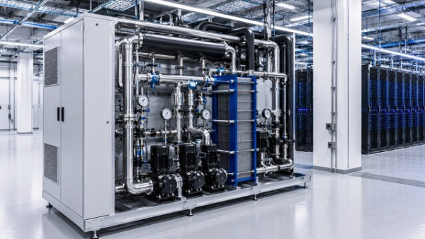
This distinction becomes more significant when the filter is integrated directly into a CDU package. A compact CDU may already have limited hydraulic margin because pressure losses are distributed across multiple components in a relatively short flow path.

The filter needs to be considered as part of the complete hydraulic path rather than as an isolated cartridge or element.

For CDU projects, BOLEFIL engineers the filter design around the required flow rate, coolant, connection size, and available hydraulic margin, with pressure-drop curves available for the selected design. These data can be incorporated into CDU system design and filter qualification.

For CDU projects, BOLEFIL engineers the filter design

Terminal Differential Pressure in CDU Operation

Particulate accumulation increases the differential pressure across the filter. When the pressure drop reaches the filter’s specified service limit, the element may need to be replaced, or the filter may need to be cleaned if it is designed for cleaning.

The specified limit may be listed as terminal differential pressure, service ΔP, or under a different name in the supplier’s documentation.

Terminal ΔP is associated with the later stage of the filter’s service cycle. It may be used as a maintenance threshold, a recommended changeout point, or another defined operating limit.

The definition matters because the value is only useful when the measurement basis is clear.

For example, a terminal differential pressure specified across a filter element is not necessarily equivalent to a differential pressure measured across the complete housing. The latter may include additional resistance from the assembly itself.

Using Filter ΔP to Monitor the Cooling Loop

Differential pressure can also provide information about changes in the cooling loop during operation.

As particles collect in the filter, the ΔP will gradually move upward. A sudden rise is a reason to check what is coming into the loop and whether the filter is seeing more solids than usual.

Commissioning is one situation where this can occur. A newly installed cooling loop may release residual material from piping, components, or flushing activities. Similar changes can occur after maintenance work on connected equipment.

The trend is more useful when viewed together with flow conditions. A change in flow rate can change the measured pressure drop even if the filter loading has not changed by the same amount.

Filter monitoring is not simply a matter of setting one pressure value and treating every increase as evidence that the filter needs immediate replacement.

Applying Pressure-Drop Data to CDU Filter Qualification

A CDU filter qualification review needs to connect filter performance data with the hydraulic conditions of the actual cooling system.

The clean pressure drop establishes the initial resistance of the filtration arrangement. Loaded pressure drop shows how that resistance develops as the filter performs its intended function. Terminal differential pressure provides the defined operating limit later in the service cycle.

These conditions should be considered against the pump operating point and the pressure losses of the rest of the TCS.

If a pressure-drop curve was generated using different flow conditions, coolant properties, filter configuration, or measurement locations, the data may not be directly transferable to the final CDU design.

For a CDU OEM or liquid cooling integrator, this becomes part of the filter qualification process rather than simply a product-selection exercise.

A filter may meet the required filtration rating while still requiring further hydraulic review before it is integrated into the final CDU configuration.

Applying Pressure-Drop Data to CDU Filter Qualification

Conclusion

CDU filter pressure drop changes as the filter moves from a clean condition toward a loaded condition. The clean value establishes the initial hydraulic resistance, while the loaded condition shows how much additional resistance develops as particulate accumulates.

For CDU filter sizing, the useful pressure-drop data extends beyond the initial clean-filter value. Flow conditions, coolant properties, filter configuration, measurement location, assembly pressure loss, and terminal differential pressure all affect how the filter behaves within the TCS.

Reviewing these conditions together provides a more realistic basis for evaluating a filter before it is integrated into a CDU and placed into service.

relevant products

Subscribe to our blog newsletter

Get the best, coolest and latest delivered to your inbox each week

[newsletter_form]

Have Questions?

error: Content is protected !!