Knowledge

Full-flow vs. side-stream filtration can involve different operating conditions even when the same filtration rating is used. The flow rate, pressure conditions, and hydraulic path through the filtration assembly change with the installation arrangement.

TCS filtration can use either a full-flow or side-stream arrangement, with different requirements for filter area, pressure drop, housing configuration, and system integration.

Full-Flow Filtration in the Main TCS Flow Path

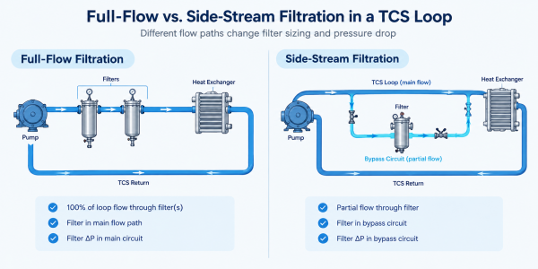
In a full-flow TCS arrangement, the filter sits in the main flow path, so the TCS flow passes through the filter during normal operation.

Filter pressure loss adds to the pressure required across the main hydraulic circuit. The available pressure has to cover the filtration assembly along with the heat exchanger, cold plates, manifolds, piping, fittings, valves, and other components in the flow path.

TCS filter capacity needs to match the actual operating flow. Higher flow through a given filter configuration generally produces higher differential pressure. As particulate accumulates in the filter media, differential pressure can increase further.

Filter area also becomes important at the design flow. If the available area is too small for the required flow, differential pressure can become a limiting factor. The filter may use a larger filtration area or multiple elements when the design flow is high. This provides more media area for the TCS flow and reduces the flow carried by each element.

Full-Flow vs. Side-Stream Filtration

Side-Stream Filtration in a Bypass Circuit

A side-stream arrangement diverts a portion of the circulating coolant from the main TCS loop through a separate filtration circuit before returning it to the loop.

The bypass flow is only a portion of the total TCS circulation flow. How much flow is sent through the filter depends on the loop and the filtration requirement. The rest of the coolant remains in the main TCS circuit.

Filter capacity and media area are sized for the bypass flow rather than the total TCS circulation flow.

Pressure drop is still a consideration in the bypass line. The filter, piping, valves, connections, and other components all add resistance to the flow, so the circuit needs enough available pressure to deliver the required bypass flow.

With only part of the TCS flow passing through the filter, the side-stream assembly can be smaller than a full-flow assembly for the same loop, provided the bypass flow and filtration duty are appropriate.

Filter Area Does Not Follow Filtration Rating Alone

A 25 µm or 50 µm filtration rating does not by itself determine the required filtration area. The filter cartridge and housing need to be selected based on the required flow and pressure-drop conditions, with enough media area to handle the application.

Flow rate is one of the main sizing variables. The same filter media can operate at different flow rates, with corresponding changes in differential pressure and particle-loading behavior.

Coolant viscosity has a direct effect on TCS filter pressure drop. A water-based coolant and a glycol-based coolant will not produce the same pressure drop at the same flow rate, and the difference can change with temperature. For a TCS application, the pressure-drop calculation needs to use the actual coolant and its operating temperature.

The amount of solids entering the filter also changes how quickly the media loads. A higher solids load means more material is retained by the filter media over the same period of operation. Differential pressure increases as that material accumulates in the media.

Where the Pressure Loss Occurs

Filter differential pressure is only one part of the hydraulic design. Its location within the TCS circuit also matters.

In a full-flow arrangement, the filtration assembly is installed directly in the main hydraulic path. Its pressure loss is part of the pressure loss of the primary circuit, along with the other components in the flow path.

In a side-stream arrangement, the filter pressure loss occurs within the bypass circuit. The primary TCS flow does not pass through the filter, while the bypass circuit requires sufficient pressure differential to maintain the specified side-stream flow.

A filter configuration that is suitable for a given side-stream flow may not be suitable for the same flow in the main TCS circuit. The available pressure-drop budget, flow rate, and filtration area all need to be evaluated for the actual installation condition.

Where the Pressure Loss Occurs

The Filtration Duty Can Change With System Operation

Filtration requirements can differ between commissioning and normal operation.

A new TCS loop can carry debris left from installation, assembly, or system flushing. Filtration during this stage is intended to remove this material before the system moves into normal operation. A temporary filter is often used for the initial flushing work and can be removed or replaced once the loop has been cleaned.

Once the system is in operation, the filtration duty changes. The focus is on keeping the coolant clean and removing particles that enter the loop or are generated during operation. Particle contamination can also contribute to cold plate fouling and restrict coolant flow.

The filter used for flushing does not have to be the same filter used afterward. The two stages can call for different filter configurations based on the flow being treated and the amount of particulate in the system.

The Housing Is Part of the Filtration Assembly

The filter element is only one part of the filtration assembly.

The housing provides the flow path around the filter element. Its internal volume and flow passages add to the pressure drop of the assembly, while the inlet and outlet arrangement determines how coolant moves through the housing.

The housing also needs to allow for element replacement, isolation, and routine maintenance within the available installation space. Seals, valves, and the element retention method form part of the same assembly.

The filter element itself may meet the required filtration rating and pressure-drop target, while the complete assembly still requires changes to the housing or internal flow arrangement for the final application.

Prototype Conditions May Not Represent the Production Design

Filtration requirements can change as a CDU design moves from testing to production.

An early prototype is not always tested under the same conditions planned for the production unit. The flow rate, connections, and filtration setup may change as the CDU design is developed.

The filtration assembly should be reviewed against the final operating conditions before the production configuration is established.

When filtration is integrated into a packaged CDU or TCS skid, the filtration assembly needs to match the hydraulic path, connection arrangement, service access, and maintenance procedure. BOLEFIL provides filtration solutions for TCS cooling circuits, including filter cartridges and assemblies configured for the required flow, filtration rating, and installation arrangement.

Full-Flow and Side-Stream Require Different Design Inputs

The same filtration rating can be used in either arrangement, but the design conditions for TCS loop filtration are different.

For a full-flow configuration, relevant inputs include:

  • TCS design and operating flow rate
  • Available pressure-drop budget
  • Coolant type and concentration
  • Operating temperature and pressure
  • Required filtration rating
  • Expected particle loading
  • Connection size and configuration
  • Element replacement or cleaning requirements

A side-stream configuration uses the same basic operating information, with the bypass flow rate as an additional design parameter. The bypass connection also has to provide enough pressure for the selected side-stream flow. Where the filtered flow returns to the TCS loop is part of the system layout.


relevant products

Subscribe to our blog newsletter

Get the best, coolest and latest delivered to your inbox each week

[newsletter_form]

Have Questions?

error: Content is protected !!